The following example demonstrates the thermal simulation of a warm water underfloor heating system. The task is to examine the temperature- as well as the energy-distribution resulting from the underfloor heating in an internal floor with wall connection.
The layout of the detail to be simulated:
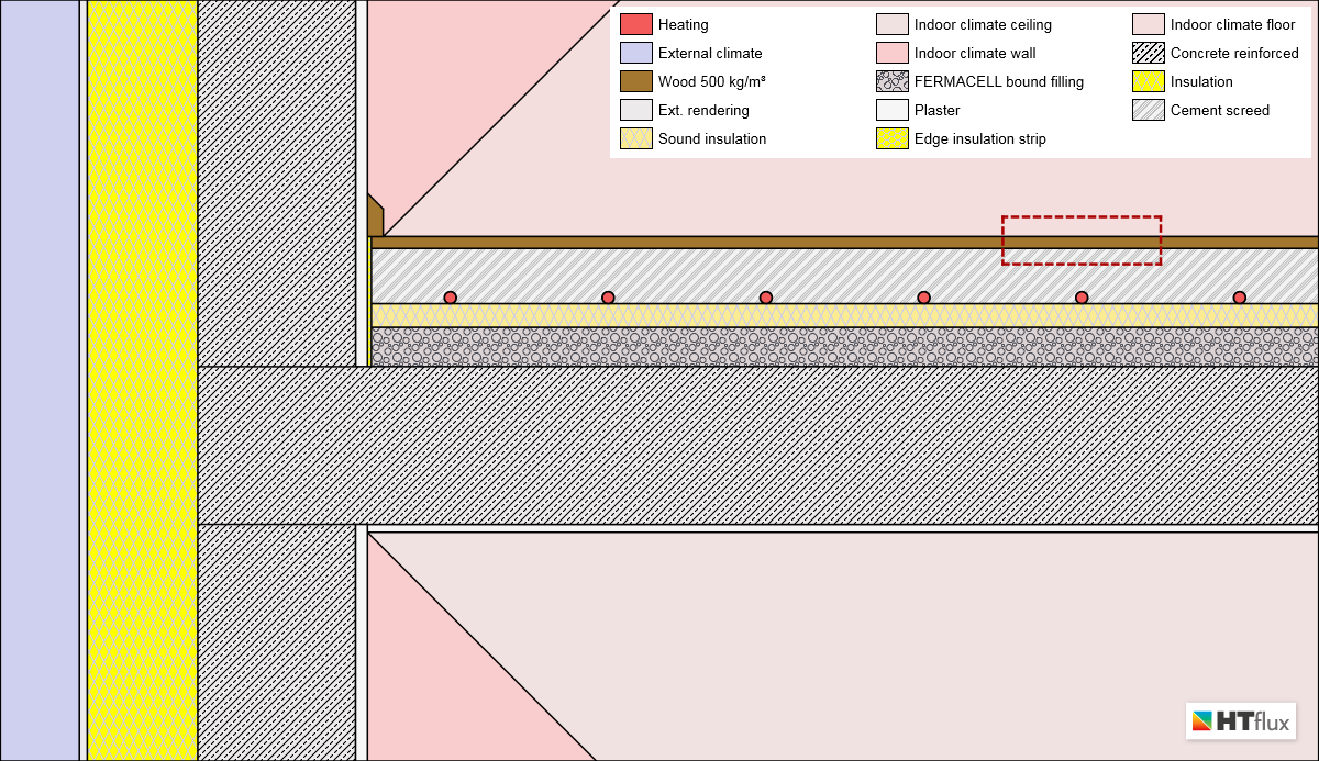
Materials view – underfloor heating simulation in an internal floor with wall connection
To process the simulation, a set of boundary conditions had to be set. Find these values at the bottom of this page.
The simulation reveals many details regarding the temperatures as well as the heat flux:
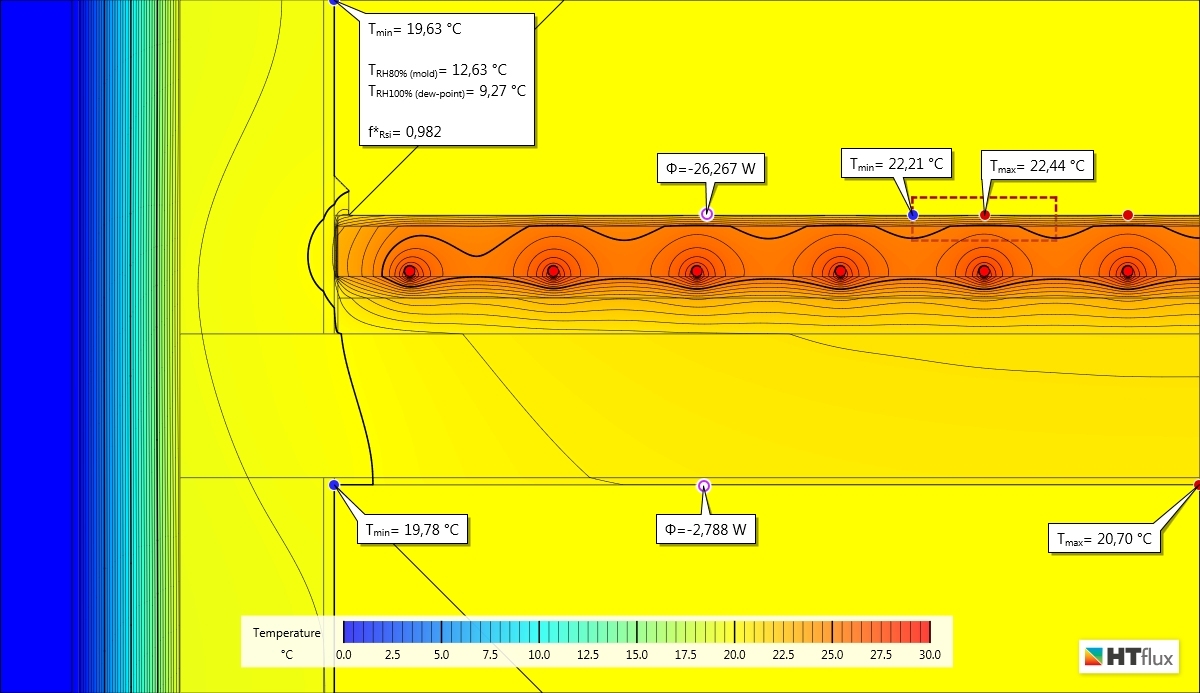
Temperature view – underfloor heating simulation
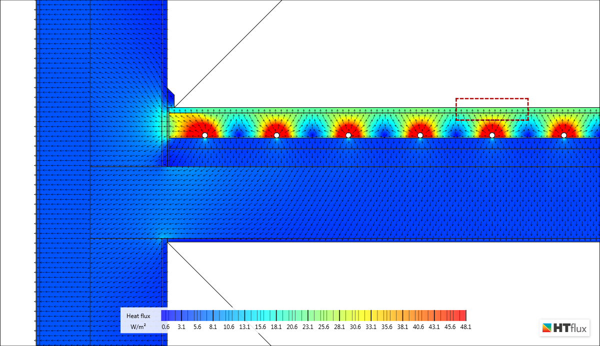
Heat flux view – underfloor heating simulation
A number of interesting new insights can be obtained of the simulation: e.g. the so-called waviness of the temperature profile of the floor can be determined. In the present example the surface temperatures of the wooden floor vary in a range from 22,2°C to 22,4°C. Hence the amplitude of the waviness is 0,2°C.
It might also be of some interest how much of the heating energy is delivered to the ceiling of the bottom floor. To calculate this portion it is necessary to redo the simulation with the heating “switched off”, keeping room temperatures at the given 20°C. Doing this we are able to determine the heat loss caused by the wall’s thermal bridging effect, on the upper floor as well as on the lower floor. These values represent the initial values to calculate the effect of the heating. The difference of these simulations values enable us to calculate the total energy input of the underfloor heating system as well as the portions distributed to the different floors.
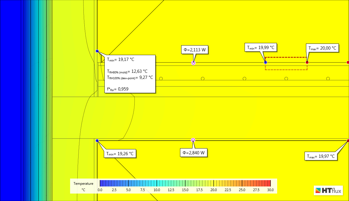
Thermal simulation – underfloor heating system turned off
Calculation of the total heat flux caused by the heating system:
| Heat flux “heating on” | Heat flux “heating off” | Heat flux caused by the heating system (difference) | |
| upper floor | -26,267 watts | 2,113 watts | -28,380 watts (83,4%) |
| lower floor | -2,788 watts | 2,840 watts | -5,628 watts (16,5%) |
| total | -29,055 watts | 4,953 watts | -34,008 watts (100%) |
Hence the total heating output of the underfloor heating system is 34 watts in the area simulated. A portion of 16,5% is distributed to the lower floor. The effective input to the upper floor is 26,3 watts (=upward heating output minus the loss due to thermal bridging). Of course the total heat flux as well as the portion is dependent on the temperatures assumed.
As always, we can use the HTflux report export feature to generate a well-structured PDF report, containing the simulation parameters as well as the desired views of the simulation:
Report thermal simulation of an underfloor heating system
Glaser 2d simulation
Using the unique Glaser-2d functionality of HTflux we can also simulate the relative humidity profile resulting of the under floor heating without any extra effort. Assuming a relative humidity of 65% for the internal climate and 80% relative humidity on the outside we obtain the following result:

Glaser 2d simulation showing the humidity profile caused by the underfloor heating
You can clearly see how the active underfloor heating causes a low humidity within the cement screed.
Parameters and boundary conditions of the simulation
Layers of the floor:
| 1,5 cm | Wood (parquet) (λ=0,13) |
| 7 cm | Cement screed (λ=0,133) |
| 3 cm | Sound insulation (λ=0,41) |
| 5 cm | bound filling (λ=0,12) |
| 20 cm | Reinforced concrete slab (λ=2,50) |
| 1 cm | Plaster (λ=0,70) |
The exterior wall is made of 20cm reinforced concrete, insulated with a 14cm EPS layer (λ=0,39).
Boundary conditions – Thermal transfer resistances:
| Wall exterior side | 0,04 m²K/W |
| Floor (upper floor) | 0,10 m²K/W |
| Ceiling (lower floor) | 0,17 m²K/W |
| Wall interior side | 0,13 m²K/W |
| Heating pipe/cement screed | 0,018 m²K/W |
Boundary conditions – Temperatures:
| Exterior temperature | 0 °C |
| Interior temperature | 20 °C |
| Water temperature (heating medium) | 30 °C |
Note: You are permitted and encouraged to use images from this page or to set a link to this page, provided that authorship is credited to “www.htflux.com”.