To demonstrate the usefulness of the new fluid-dynamic calculation tool, we present a simple but very interesting application. Of course, the method and tool described can be used to simulate the heat transfer of flows of all kinds of fluids such as air, gas, water, oil, refrigerant etc.
The chimney model simulated
In this example, we use the tool to perform a thermal simulation of a chimney containing a flue pipe, as well as an integrated combustion air intake channel. We assume the chimney is free standing and running through a conditioned room having a temperatur of 23 °C. The chimney is fomed by a pre-cast brick made of two different types of lightweight insulating concrete. The flue pipe is made of stainless-steel, whereas the combustion air channel is formed simply as a cavity within the brick. The air gap surrounding the steel-pipe is simulated using HTflux’s automated ISO 6946 cavity tool. On external (room) side the chimney brick is covered with 1,5 cm cement-lime plaster.
The diameter of the flue pipe is 30 cm, the one of the fresh air channel is 20 cm.

Heat transfer of flue gas and combustion air
The actual thermal simulation is an easy straight-forward task, which can be carried out within minutes using HTflux. The tricky – and crucial – part regarding the simulation is to describe the heat transfer of the flowing gases, flue gas as well as fresh air, correctly. However with the integration of the new pipe flow calculation feature in HTflux this job becomes an easy task also. Using this approach the heat transfer can be modelled with a simple boundary condition defined by the average gas temperature and a surface resistance value that reflects the entire heat transfer coefficient (as a result of the the fluid dynamical calculations).
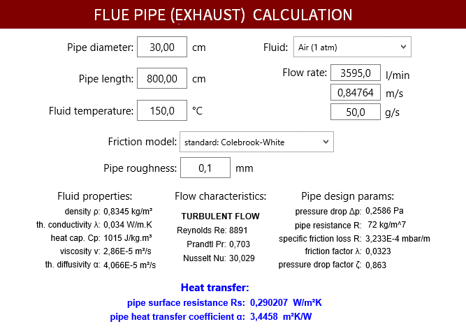
For the calculation it is necessary to provide the correct flow rates. This can be done by specifiying the volumetric flow-rate, the average flow-speed or the mass flow-rate. For this application the third option might be the easiest approach. Based on the specification of the heating system we assume a flue mass-flow rate of 50 grams per second. Further an oil-consumption rate of 2,5 grams per second and an average flue gas temperature of 140 °C is specified for the boiler. Assuming that the whole combustion air is taken of the supply channel, we can estimate an average mass-flow of 47,5 grams per second on the combustion air side.
Of course the actual temperatures will vary within the chimney. We therefore estimate average values at the relevant position. After performing the thermal simulation, the resulting heat exchange rates could be used to calculate the effective vertical temperature profile for the chimney channels. For higher precision the simulation could then be redone with correct temperatures for the flue gas and supply air.
In the pipe flow calculation tool of HTflux we choose “Air” as type of the fluid. Actually, the flue gas will have slightly different properties, depending on the specific kind of combustion and water vapor content. However for the calculation of the pipe flow heat-transfer coefficient the selection of Air as medium will lead to sufficiently precise results. Finally, we have to provide a roughness for the flue pipe and air supply channel based on the specifications of the chimney.
For both channels, the fluid-dynamical calculation results, as well as the input parameters can be seen here (click to enlarge):

Thermal simulation results
The actual simulation takes only few seconds and leads to the following results:
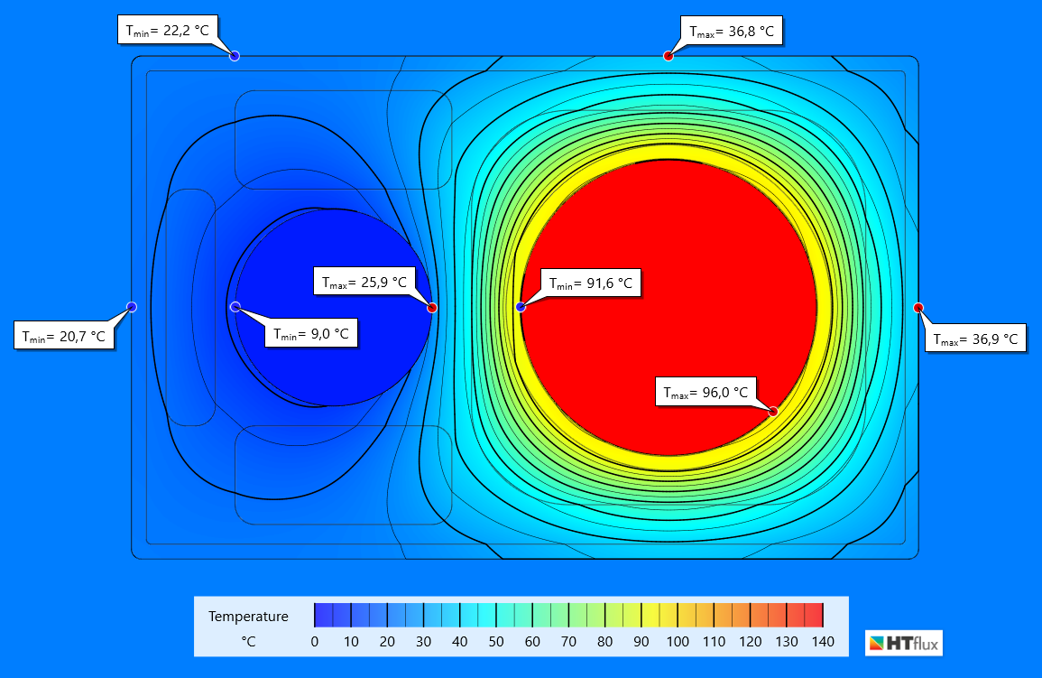
Thermal view of the chimney simulation (left: air intake; right: flue pipe)
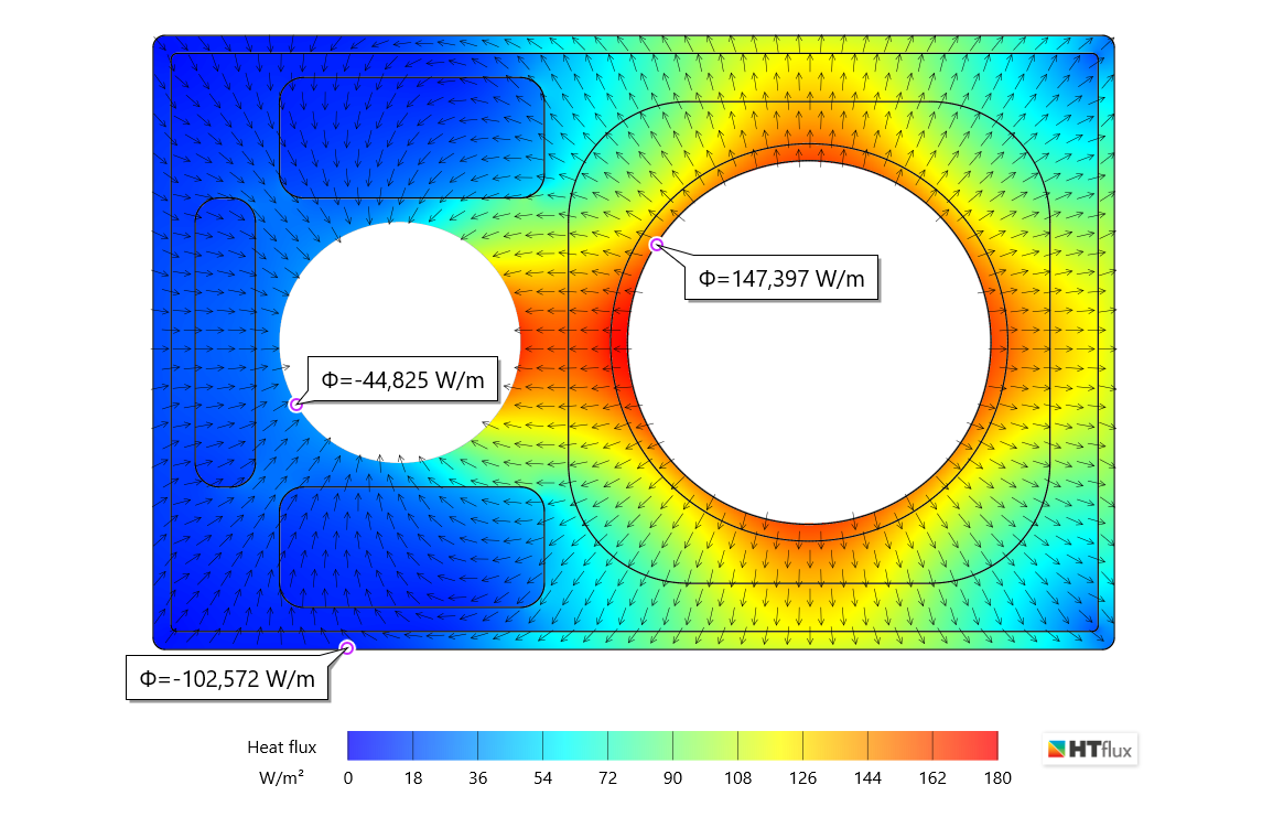
Heat-flux view of the chimney with total heat-flux measurement results for supply air channel, flue pipe and surrounding room
After-MATH
Based on the simulations numerous studies and optimizations could be carried out this detail, e.g. regarding the following topics:
- Heat transfer to ambience (heat loss / gain)
- Heat transfer from flue-pipe to air supply (pre-heating of combustion air)
- Minimum surface temperature of chimney on cold-air side
- Maximum surface temperature of chimney on hot flue gas side
- Maximum surface temperature for specific materials
- Flue gas condensation risk: minimum temperature of the internal surface of the flue pipe
- Optimization of insulation layers and required material properties
- …
In this article, we will only focus on the heat exchange among the flue-pipe, fresh air channel and ambience of the chimney (heated room).
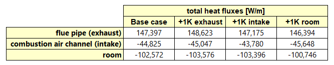
In order to do so, we use a simple, but powerful method to determine the heat exchange rates among these three regions. First, we repeat the thermal simulation three times, varying the temperature of each region by 1 degree Kelvin. By doing this we get the following total heat fluxes for the three regions (simulation cases in columns):
Note:
- the heat-fluxes are measured from the boundary into the materials, therefore a positive value means a heat loss in this table, whereas a negative value represents a heat gain.
- all heat-flux and heat exchange figures are valid for a length of 1 meter of the chimney.
- to keep this study simple, we have replaced the dynamic air-cavity material (around the pipe) with a “constant material” having the same thermal conductivity, as for the sake of simplicity we will not focus on the non-linear behaviour of the heat-exchange within the cavity.
- for a very detailed study considering all non-linear effects the whole process would have to be repeated with different temperatures and flow-rates for the combustion air and flue gas.
Finally, all we have to do is to subtract the heat-fluxes from the actual base-case values and divide this value by the temperature difference applied (here it is 1K, so we can omit this step).
By doing this we get the following heat-exchange rates:

These heat-exchanges rates are very useful to describe the entire heat-balance of the whole system, e.g. they be used to calculate a vertical temperature profile of the whole chimney. Some simple conclusions that can be drawn from the table above are (all relevant for 1 meter of the chimney construction):
- For every degree that the flue gas is hotter than the room temperature, it loses 1,003 Watts to the room (actually this should be seen as a gain for the room)
- For every degree that the flue gas is hotter than the intake, it will heat the combustion air with a power of 0,222 Watts. So, in our example (using the temperatures above), the combustion air is pre-heated with 30,0 Watts coming from the flue gas flow and 14,8 Watts coming from the surrounding room.
- The room loses 0,823 Watts to the air intake channel for every degree that the fresh air is cooler than the room temperature.
- …
(c) HTflux, Daniel Rüdisser
Note: You are permitted and encouraged to use images from this page or to set a link to this page, provided that authorship is credited to “www.htflux.com”.