The following practical example demonstrates how HTflux can be used to efficiently analyze even complex details with little effort. The details shows the connection of a PVC window to a timber frame wall. A comprehensive assessment regarding the condensation risk of the detail can easily be performed using HTflux unique Glaser-2d function.
The window frame was imported of a manufacturer CAD file using the DXF file format. The wall was drawn inside HTflux using the drawing functions. The glazing was created using the HTflux glazing-tool.
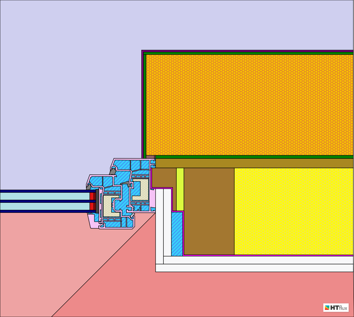
the window connection being analyzed
The climatic boundary conditions can been defined according to local standards or conditions. In this example an external temperature of -5°C and relative humidity of 80% and 20°C / 60% for the internal climate has been chosen. In accordance with ISO 13788 the thermal surface resistance for the window has been set to 0,13 m²K/W and 0,25 m²K/W for the wall surface.
After assigning all materials to the objects, the thermal simulation can be performed. By using the surface temperature tools, the minimum temperatures of certain surfaces and material interfaces can be determined automatically.
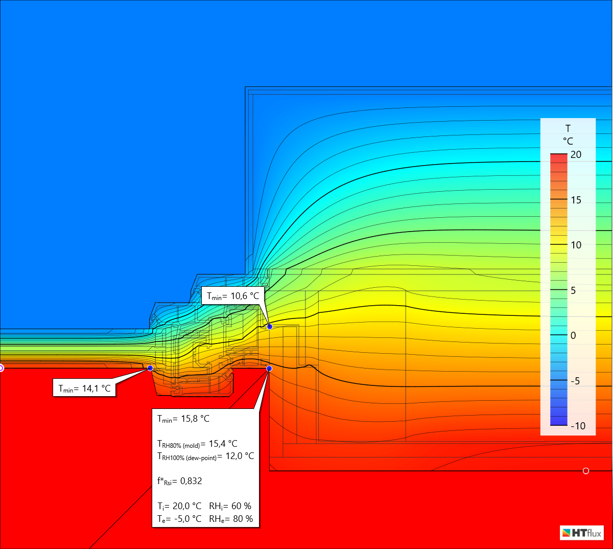
temperature view of the window connection detail showing minimum surface temperatures
HTflux is also able to calculate the minimum surface temperatures for mold or condensation risks. In this example the lowest temperature of the gypsum plaster boards reaches 15,8°C, still being higher than the mold-temperature, calculated according to the standard.
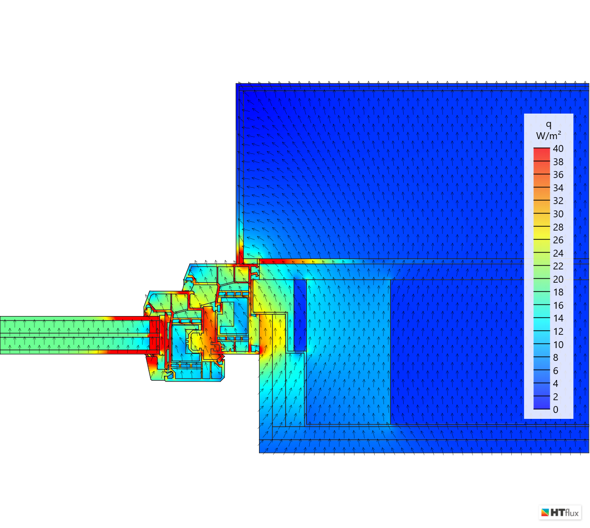
the heat-flux view can be used to minimize thermal bridging at the window connection
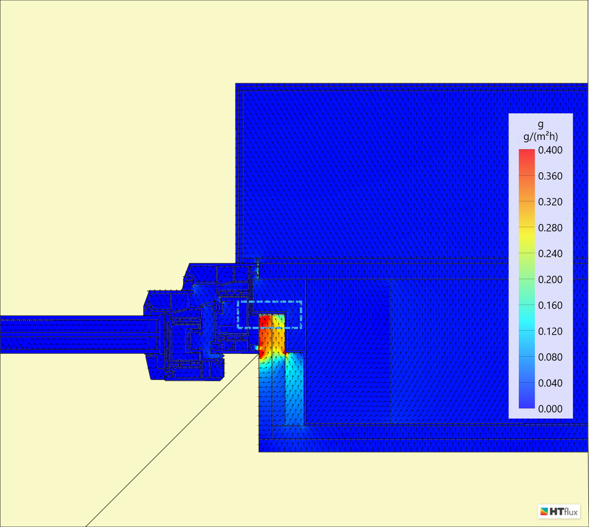
Fortunately with HTflux the hygro-thermal assessment does not stop at this point – by using the Glaser-2d feature water vapor streams can be simulated easily. In this example the Glaser-2d simulation reveals the risk of condensation in the gypsum plaster-boards below the window frame.

Glaser-2d reveals condensation risk behind the window frame
The condensation amount is little as the simulation is based on the assumption that the all elements fit tightly. However any gaps, e.g. between the gypsum boards and the window frame would lead to a significant increase in condensation.
In the region of the window frame the vapor barrier has been placed too far inside the wall. This can be seen very well using the Vapor Pressure View:
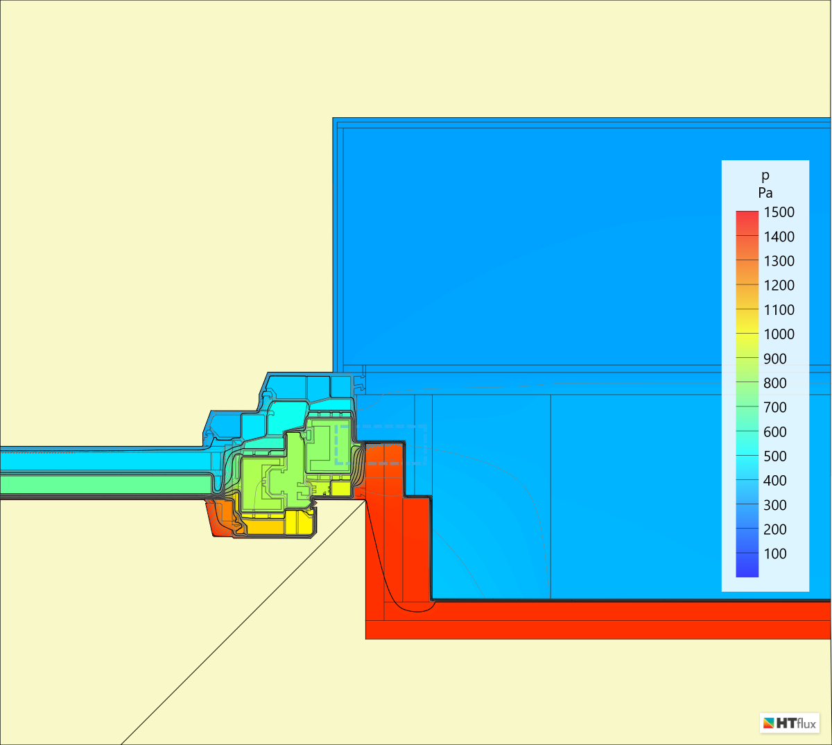
In the vapor pressure view the drop of the water vapor pressure at the vapor barrier can be seen
The Vapor Flux View can used to analyze the path of the vapor to the condensation spot. The humidity travels through the gypsum plaster boards, as well as through the air cavity in the corner of the wall:
the water vapor stream inside the gypsum plaster boards leads to condensation on the vapor barrier
Now that the problem has been identified, HTflux can be used to modify the detail in a way that no condensation will occur.
Author: DI Daniel Rüdisser, HTflux
Note: You are permitted and encouraged to use images from this page or to set a link to this page, provided that authorship is credited to “www.htflux.com”.