Heat transfer resistance / surface resistance
(brief) Theory
The thermal transfer resistance or surface resistance is the reciprocal value of the heat transfer coefficient (R=1/h). Its SI unit is (m².K)/W. It’s usually a constant value describing the heat transfer from an environment into or out of the surface of a building component. It represents a simplified model, as the actual heat exchange occurs due to a combination of the three different physical processes:
|
 |
The underlying simplified model consists of two heat transfer coefficients, describing the heat transfer by radiation (hr) and by convection and conduction (hc):

For internal surfaces usually radiation plays the predominant role. For external surfaces the heat transfer through convection becomes the prevailing process as higher average air speed is assumed.
Practice
When performing building science simulations you will usually have to use the surface resistance values as defined in the specific national and international standards, such as ISO 6946. Taking into account the differing convective situation (“warm air rises, cold air stays on the bottom”) and the different levels of air speed it is necessary to choose the appropriate value for each surface. Using HTflux you can either directly key in the desired value or you can open a convenient tool dialog, that will assist you to find the correct value.
The following sections provide a brief of overview of surface resistance values commonly used in building science:
Internal surface resistances
| value | standard | application |
| 0,13 m²K/W | ISO 6946 | horizontal, undefined or changing heat-flux direction e.g. between two heated floors or internal surface of outer wall |
| 0,10 m²K/W | ISO 6946 | upward heat-flux, increased heat transfer e.g. internal ceiling below unheated room or flat-roof |
| 0,17 m²K/W | ISO 6946 | downward heat-flux, decreased heat transfer e.g. internal floor above unheated room |
| 0,25 m²K/W | ISO 13788 | worst-case surface resistance for hygrothermal calculations e.g. to determine the minimum surface temperature (condensation risk) |
| 0,20 m²K/W | ISO 10077-2 | reduced radiation/convection in edges or junctions |
External surface resistances
| value | standard | application |
| 0,04 m²K/W | ISO 6946 | Most external surfaces e.g. external side of exterior wall |
| 0,13 m²K/W | ISO 6946 | horizontal or changing heat-flux direction to ventilated layer or unheated room e.g. outer side of ventilated exterior wall |
| 0,10 m²K/W | ISO 6946 | downward heat-flux, to ventilated roof-space or unheated room e.g. floor of unheated room on top of heated room |
| 0,17 m²K/W | ISO 6946 | upward heat-flux, to ventilated floor space or unheated room e.g. ceiling of unheated room below heated room |
Graphical overview
The following image provides a graphical overview of commonly used surface resistances:
(you will also find this image on the third page of the heat transfer tool dialog).
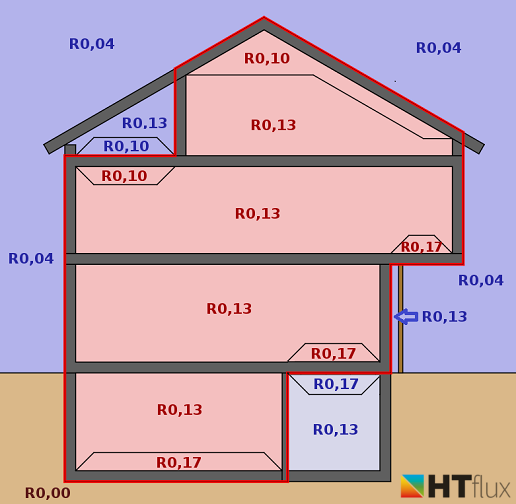
Overview of standard surface resistances Rsi, Rse (c) HTflux
Customized, specific surface resistances
For special purposes (e.g. high radiation temperature, low emissivity surfaces, high wind-speeds…) it is possible to use different surface resistances. These can be calculated based on the methods described in the appendix A of ISO 6946. HTflux offers a very convenient tool for this purpose. You will find this feature on the second page of the heat transfer resistance tool dialog.
Surface resistances for the simulation of surface embedded heating or cooling systems
The values presented in this section should be applied for thermal simulation of embedded surface heating or cooling elements (e.g. standard floor heatings). Note: the values should only be applied for the simulation of ACTIVE heating or cooling elements. All standard calculations regarding heat transmission (U-values, PSI-values and alike) have to be done WITHOUT such active elements. For this purpose you will have to use the values described on top of this page.
The values below are based on the standard EN 1264-5 – Water based surface embedded heating and cooling systems – Part 5: Heating and cooling surfaces embedded in floors, ceilings and walls – Determination of the thermal output.
| value | standard | application |
| 0,0926 m²K/W | EN 1264-5 | Surface embedded heating – FLOOR (surface temperature of floor is higher than room temperature) |
| 0,125 m²K/W | EN 1264-5 | Surface embedded heating – WALL (surface temperature of wall is higher than room temperature) |
| 0,1538 m²K/W | EN 1264-5 | Surface embedded heating – CEILING (surface temperature of ceiling is higher than room temperature) |
| 0,1538 m²K/W | EN 1264-5 | Surface embedded cooling – FLOOR (surface temperature of floor is lower than room temperature) |
| 0,125 m²K/W | EN 1264-5 | Surface embedded cooling – WALL (surface temperature of wall is lower than room temperature) |
| 0,0926 m²K/W | EN 1264-5 | Surface embedded cooling – CEILING (surface temperature of ceiling is lower than room temperature) |
Note: since HTflux requires the entry of heat transfer resistances, the values presented in the table are the reciprocals of the heat transfer coefficients as defined in the standard (10,8 m²K/W, 8 m²K/W, 6,5 m²K/W).
Heat transfer of pipes with flowing fluids (liquids or gases)
On the last tab of the heat-transfer tool dialog you will find a versatile tool that allows you to calculate heat transfer coefficients for pipes containing liquids (water, refrigerant, oil,…) or gases (air, vapors,…).
The tool and the underlying flud dynamical calculations is explained here: Heat transfer of pipe flows