U-value tool
The measurement function U-value is a versatile tool, which can be used for multiple purposes:
- determination of 1d U-values (=calculation based on the R-values of the layers)
- determination of 2d U-values (=calculation based of heat-flux measurement)
- documenting the structural layers
- displaying the R value
- displaying dynamic thermal key-figures (areal heat capacity, thermal mass, phase shifts,…)
U-value 1d – analytic calculation method
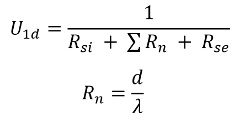
In HTflux the 1d (=one dimensional) U value refers to thermal transmittance calculated based on the thermal resistances of the layers of a building component. To obtain the R-value of a building component the thermal resistances of each layer have to be added, including the surface resistances on each side. The U-value is the reciprocal value of this total R-value (U=1/R). The formula for the U-value can therefore be written as:
 |
Rsi ….internal surface resistance Rse ….external surface resistance Rn ….thermal resistance of layer n d ….thickness of layer λ ….thermal conductivity of layer |
This method implies that the building element consists solely of plane, uniform and parallel layers. If you have to consider non-uniformities (such as infills, joints, joists,…) you can “correct” the conductivities of the specific layers by using the rules described in ISO 6946. In most cases it will be easier and more precise to use the 2d-method described below.
U-value 2d – numerical/heat flux method
In HTflux the term 2d (=two dimensional) U-value refers to the thermal transmittance calculated based on a (numerical) heat-flux measurement. Using this method it is quite easy to obtain the U-value of non-uniform building components. Using this method the U-value can be described as:
 |
Φ ….total heat-flux in specified section A ….surface of specified section ΔT ….applied temperature difference |
The 2d-U-value and the 1d-U-value will match on components built solely of plane and uniform layers, provided that the 2d-value is determined in an area not affected by any thermal bridging effects nearby. To determine the heat flux used to calculate the U-value the software will automatically “measure” the heat-flux on both sides of the component and use the mean value of these measurements. This will increase the precision of the calculation. However, if unaffected by any thermal bridging, the heat-flux values on either side of the component will match.
Applying the U-value tool
Launch the tool by clicking on the appropriate button located in the top menu Measurements:


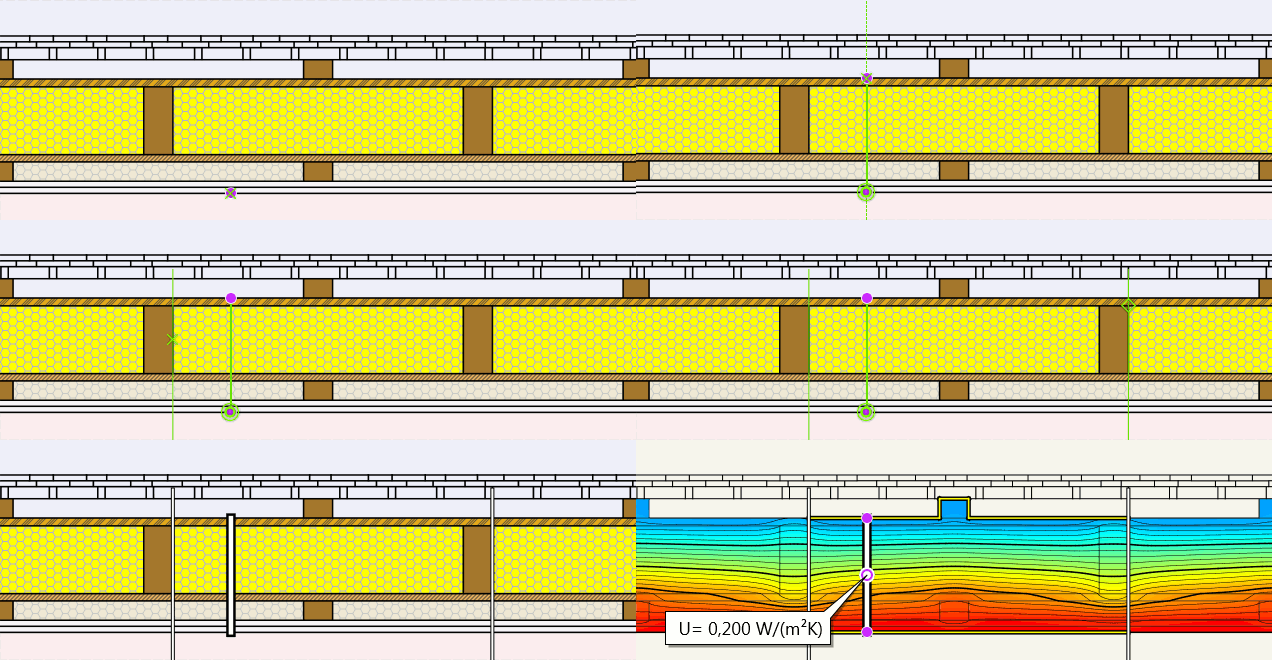
- Pick an appropriate point either on the external or on the internal side of the component. It is important to pick this point directly on the surface of the component, this means on the layer touching the boundary condition (external or internal climate).
- Now “cut through” the component, perpendicular to its surface. This means pick a point on the opposite surface of the component touching the other boundary condition (internal or external).
(note. to support you in placing the U-value tool, the angle-snap tool will be activated automatically. If you have a component that is oriented other than in a straight horizontal or vertical position you can set up a custom angle in the snapping tool. This will allow you to align the tool more easily.) - Next you will have to define a region for the heat flux measurement (2d U-value).
The procedure will slightly differ depending on your choice of the tool:
- symmetric tool:
Select a point of your component defining the edge of the region for the heat-flux measurement. Alternatively you can type in the length of the measurement region. Note that the value typed in will reference to one side of the measurement region. To other side will be set automatically to have the same distance. - asymmetric tool:
Select an appropriate point to define the edge of the measurement region, or type in the distance in the command line. Next repeat the graphic or numeric input for the other edge of the measurement region. The heat-flux to determine the U-value will be measured between these to legs, that you have defined.
Regarding the determination of the U-value of non-uniform building elements, you can find more information here.

The measurement tool is now fully defined. To process the actual calculation and see the U-value you will have run or re-run the thermal simulation (“T-stationary” button).
Like in all measurement functions the actual results of the measurement will be displayed with by measurement tag in the graphics window.
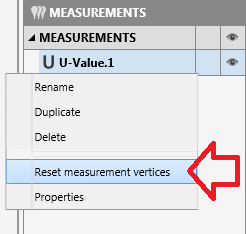
If change the dimensions the building component later on, you will either have to re-set the measurement vertices of the tool, or you can apply a new tool. To re-set the tool just select the according function in the context-menu (right-click on the tool in the project-manager):

U-value tool – options
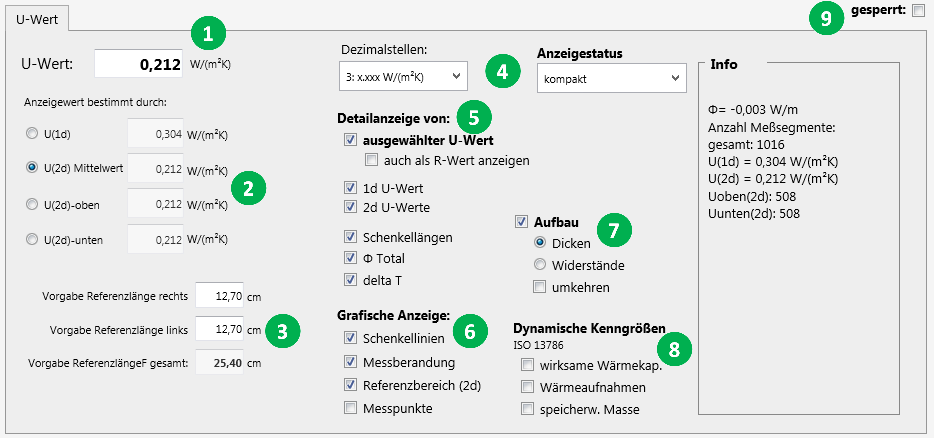
By double-clicking on the on measurement tag or on the according tool in the project-manager you will open up the settings dialog of the U-value tool.
Here you can customize the tool to your needs.

- This entry shows you the value of the currently selected type of U-value.
- Here you can choose the method how the U-value shall be calculated.
Make sure to select the 2d option when determining the U-value of a non-uniform component (see above). - These inputs allow you to check and even edit the distances chosen to calculate the 2d-U-value. If you edit the values you will have to re-run the simulation to refresh the results.
- You can change the displayed number of decimal places of the result.
- This section allows you to customize the additional information displayed when the measurement tag is in detailed results mode.
- You can alter the graphical representation of the tool here. Toggle the visibilty of certain elements.
- Here you can select if and how the layers of your component should be described in tabular form. This feature will allow you to document your building componenent very efficiently.
Tip: by turning off the visibility of all other components you can also use the U-value tool soley for the purpose of describing structural layers. - The U-value to tool can also calculate and display dynamic thermal performance figures of your component.
A detailed description of these values can be found here or in the standard ISO 13786. - If working with multiple simulation regions or on more complex simulations it might be necessary to “freeze” the results of the tool. By setting a checkmark here you will prevent recalculation of the results on further simulations.
